Product Category Product CategoryLink |
|
Home > Products > Smart Bms LiFePo4 4S 12V 200A with UART Iinterface Matching Cable
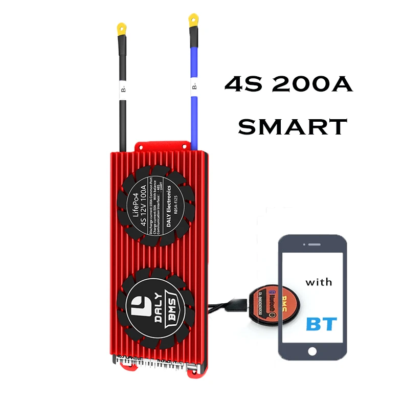
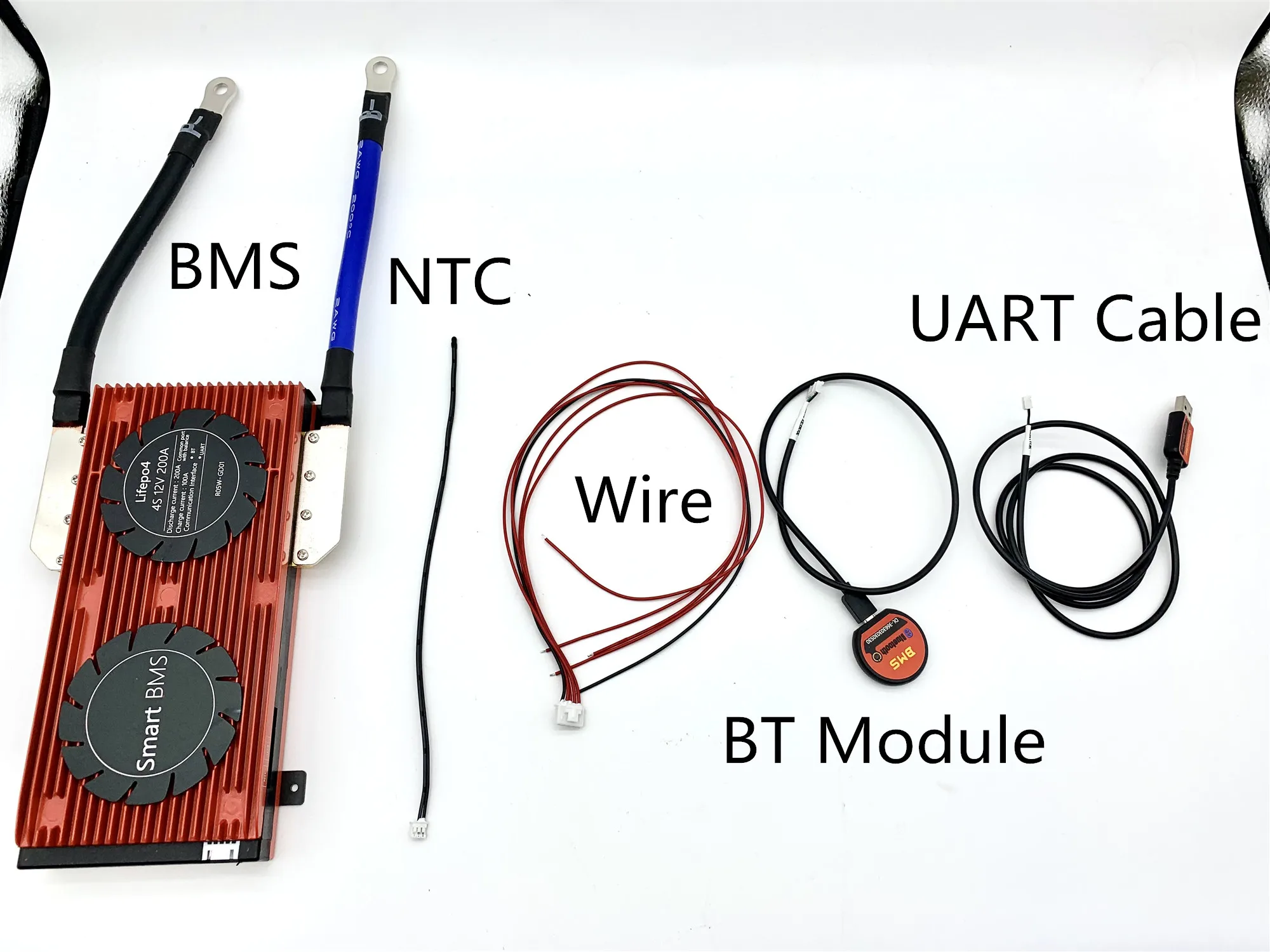
Smart Bms LiFePo4 4S 12V 200A with UART Iinterface Matching Cable
 Click on the image to view the original image |
|
| Product: |
views:50Smart Bms LiFePo4 4S 12V 200A with UART Iinterface Matching Cable |
| Unit Price: |
Negotiated |
| Min.Order: |
|
| Supply: |
|
| Delivery: |
Shipment within days since the date of payment |
| Valid until: |
Long Term |
| Updated on: |
2021-12-28 12:28 |
| |
 |
|
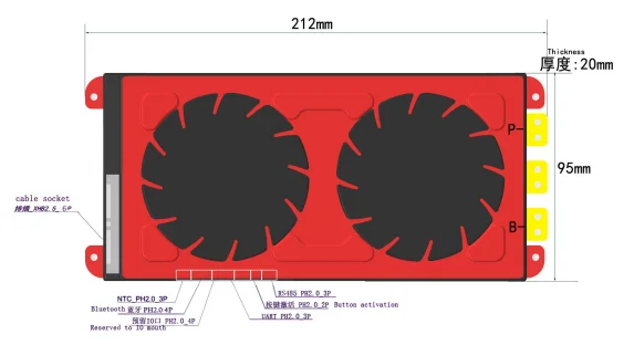
| | | 4 red wires(positive wires)+1 black wire(negative wire) | | 2 black wires fuse into 1 temperature sensor | | ① Negative wire: black color(B-) ;② Positive wire: red color(From B1 to last one all are positive wires) | | ① Bluetooth communication Receiving end ;② Bluetooth communication Sending end ; ③ Bluetooth module power supply 3.3 V | | ① UART communication Receiving end;② UART communication Sending end | | | Bluetooth,UART, GPS, LCD all are use the same port.(UART interface) If you need all of them communications, you only can use it one by one. | |
If you want to know more, you can contact us at any time,thank you! Continue discharge current | 200A | Charge voltage | 14.6V | Charge current | 100A | Working Temp Range | -20~70℃ | Storing Temp Range | -20~70℃ | Charge Temperature protection degrees | -40~80℃ |
Advantage1.Use top quality (A-level) protective integrated circuit IC, from the solution of Seiko of Japan.
2.Strong load ability, constant discharge current 18A/25/35A/45A/60A , use high voltage resistance, low inner resistance power Mosfet. The heat sink will greatly help cooling.
3.IC itself has power balancing function. The circuit is simple and reliable.
4.Typical voltage detection for each cell. So each battery will be prevented over charged or over discharged. Over current and short circuit protection function is very reliable.Long time short circuit of the load won’t affect the PCB and the battery.Temperature protection during charging and discharging.
5.Extreme low power consumption. The consumption of the whole device is less than 50uA.
6.PCB use high anti-corrosion, high water resistance, high impedance ESD conformal Coating
① Lithium battery BMS with different voltage range which can not be mixed using, Life Po4 BMS can not be used for Li-ion battery;② Cables from different manufacturers are not common ones, please make sure to use Daly’s matching cable; ③ When testing, installing, contacting, and using the protective board, take measures to put static electricity on it; ④ Mustn’t let the heat dissipation surface of the protection board directly contact the battery core, otherwise the heat will be transmitted to the battery core, which will affect the safety of the battery;
⑤ Do not disassemble or change the components of the protection board by yourself;
⑥ The metal heat sink of the protection board of the company is anodized and insulated, and the oxide layer will still be conductive after being destroyed.Avoid contact between the heat sink and the battery core and the nickel strip;
⑦ If the protection board is abnormal, please stop using it. Then use it again after it is checked with OK;
⑧ Do not use the two protective boards in series or in parallelFAQ 1.What is the common port and separate port? what is the difference?
We take 13S48V16A BMS as an example, common port 16A means your charge cathode and discharge cathode are connected in the same point end(our P-), charge cathode and discharge cathode are used in the common connection port, so the charge current and discharge current are the same 16A. while the separate port is separately connected by charge cathode (C-) and discharge cathode (P-), so the charge current and discharge current are different, discharge current 16A, charge current 8A.
2.What is the balance function?
The working principle and function are as followings, when your one cell voltage is upto alarm voltage(Li-ion upto 4.18V, LiFePo4 upto (3.6V), then the cell Balance starts to work, balance resistance starts discharge with 35ma(when balance discharge starts to work, BMS will starts a little heat up, which is the normal reflection), the cell is in both charging and discharging status, and others which are not reached to alarm voltage(Li-ion 4.18V, LiFePo43.6V)are only in charging status, no discharging, when the fast cell voltage is reached to alarm voltage (Li-ion 4.25V, Life Po43.75V)BMS starts off power protection, all the other cells are all in stop of charging, this process will enable your battery charging in balance current, and your battery voltage are in balance status, but when your cell voltage difference are in a big range, then balance can not be functionning well.
3.The relationship between Battery capacity and BMS current?
There is no direct relationship between Battery capacity and BMS current, big capacity doesn`t mean a big battery, but rely on continue current, that is to say if your engine is powerful, your should choose high current of BMS, it is not relied on battery capacity.
4. What type of charger should I choose?
Lithium battery must choose specific charger, do not use Charger for Leadacid battery, for leadacid charger may have MOS with high pressure breakdown protection, which will not protect of BMS over charge. Life Po4 battery charger voltage=battery string No.X3.6V, while Li-ion battery charger voltage=Battery string No.X4.2V.
5. What current BMS should I choose ?
Take 10S36V as an example: what current BMS you choose is relied on your E-bicycle Motor power and current limitation of controller. eg., choose 16A for below 350W, 25A for below500W, 35A for below 800W, 60A for Below 1000W, higher than 1200W are contact with our service specialist for suggestions, one inall, continue current shall be higher than current limitation in Controller.
6. Whether my BMS damaged?
If you want to judge if the BMS is damaged, please take the folowing steps, to test if each cell voltage is the same with voltmeter? if the cell voltage difference is over 1.0V, the fault is displayed that it cannot run far, no power supply at the start range, short charge time, all these issues are almost caused by battery cells, if BMS damaged is displyed as no charge, no
discharge, no discharge while the battery has voltage.
|