

If you've got a laptop computer or a cellphone that flips open like a clamshell, you've probably noticed that it senses when you open and close it and switches on or off accordingly. But how does it know? Some kind of switch wired to the hinge so it can detect the opening and closing movement? If that's what you think, you're at least half right! Think about it more carefully and you'll see a standard switch would be quite tricky to wire up in that way—and probably quite unreliable too: all that opening and closing would quickly wear it out. So, instead, many laptops and phones use an inexpensive and very reliable device called a reed switch that turns on or off when a magnet is nearby. Intruder alarms and model railroads often use them too. Let's take a closer look at how they work!
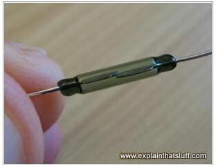
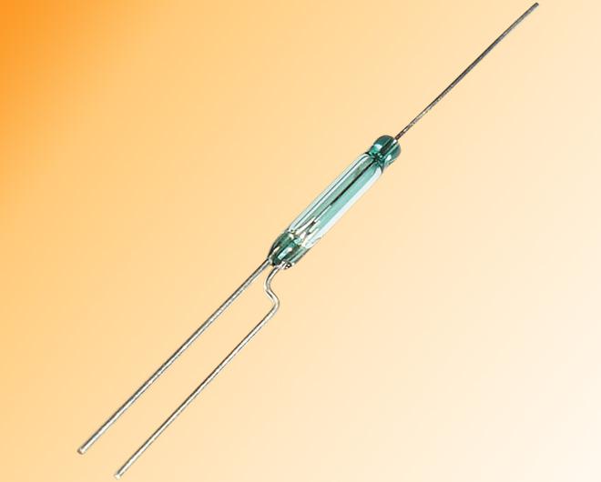
Photo: A typical reed switch (a Comus RI-23). You can just see the two overlapping metal contacts (reeds) inside the glass envelope. The contacts spring together and touch when the switch is "on"; they spring apart and interrupt the circuit when the switch is "off."
Switches that work as detectors
A finger pushing on the doorbell outside someone's house.
A switch is like a drawbridge in an electric circuit. When the switch is closed, the "bridge" is down and electric current can flow around the circuit; when the switch opens, the "bridge" is up and no current flows. So the purpose of a switch is to activate or deactivate a circuit at a time of our choosing.
Most of the electrical switches we encounter are ones we control ourselves. If you want light in a room, you flick a switch on the wall. Want to watch TV? Turn on the switch. Want to listen to your iPod? Push the wheel at the front and that activates a switch that turns on the power. But sometimes we want electrical and electronic circuits to be activated in other ways.
Suppose you want to wire up a bank safe so it triggers an alarm whenever the door opens. How would that work in practice? You'd need electrical contacts on both parts of the door frame so when the door opened the circuit would be broken, triggering the alarm. But think how tricky it would be to make a reliable electrical connection on a door frame. What if you painted over it? What if it got dirty? And wouldn't it be so obvious to a thief that they'd be able to disable it quite easily? There are lots of ways in which the electrical contact could be rendered inactive and useless. This is where reed switches can help.
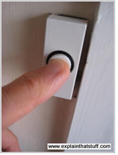
Photo: A "push-to-make" switch makes a connection and completes a circuit when you push it in; a spring makes it pop back out again when you take your finger away. A reed switch switches a current on the same way, but a magnet provides the "pushing pressure" instead of your finger.
What is a reed switch?
An ordinary switch has two electrical contacts in it that join together when you push a button and spring apart when you release it. Rocker switches on wall lights (like the one in the photo up above) push the two contacts together when the switch is in one position and pull them apart when the switch flicks the other way.
How does a reed switch work?
Reed switches come in two varieties called normally open (normally switched off) and normally closed (normally switched on).
Normally open (Form A)
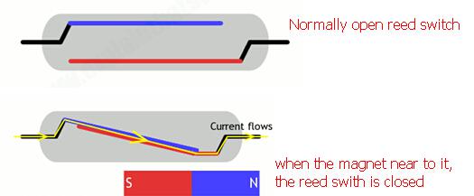
In a reed switch, the two contacts (which look like metal reeds) are made from magnetic material and housed inside a thin glass envelope. (You can see this quite clearly in our top photo.) One of the contacts (sometimes called "blades") is a magnetic north pole, while the other is a south pole. As you bring a magnet up to the switch, it affects the contacts in opposite ways, attracting one and repelling the other, so they spring together and a current flows through them. A reed switch like this is normally open (NO) (normally off), unless a magnet is positioned right next to it, when it switches on.
Take the magnet away and the contacts—made from fairly stiff and springy metal—push apart again and return back to their original positions.
Normally closed (Form B)
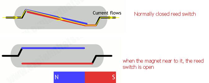
Animated drawing showing how a normally closed reed switch opens and closes when a magnet approaches or moves away.
You can also get reed switches that work the opposite way. The two contacts are normally snapped together. When you bring a magnet up to the switch, the lower contact is attracted to the magnet, the upper one is repelled, so the contacts split apart, opening the switch and breaking the circuit. Reed switches like this are called normally closed (NC) (normally switched on), and they switch off when you bring a magnet up to them.
Although reed switches can be designed in various ways, generally both contacts move (not just one) and they make a flat, parallel area of contact with one another (rather than simply touching at a point), because that helps to extend the life and reliability of the switch. Also, where I've exaggerated the movement of the contacts to make it easier to see, real reed switches have contacts that are only a few microns (millionths of a meter) apart—roughly ten times thinner than a human hair—so the movement isn't visible to the naked eye.
Reed Switch Form C
FORM C: SINGLE PULL-DOUBLE THROW (SPDT), NORMALLY OPEN/NORMALLY CLOSED (NO/NC)

The Form C reed switch configuration is also quite common. A Form C switch has three contacts, a Common and one each, Normally Open and Normally Closed. Essentially, a Form C switch has the capability of both a Form A and Form B switch in a single package. In its default state, electricity flows from the Common contact through the Normally Closed contact. Upon introduction of a magnetic field, the Common contact moves from the Normally Closed contact to the Normally Open contact, opening one circuit and closing the other, thus redirecting the flow of electricity.
Removal of the magnetic field will cause the Common contact to revert back to its initial Normally Closed position. Unlike either the Form A or Form B switch, direction of electrical flow should be considered when wiring a Form C switch, for typical SPDT functionality the electrical source would be attached to the Common lead. That is not to say that a configuration where switching between two electrical sources on the NO and NC leads to the Common lead is not possible, it simply is not the norm.