The connector industry is very large, and there are many types, such as internal IT host connectors, host peripheral connectors (I/O), device connectors, mobile phone connectors, industrial connectors, and automotive connectors. Through the communication with the predecessors of the connector and the collection of relevant market information, we will work with you to understand the basic connectors.
01. Basic introduction to the connector
What is a connector? A connector is a component that our electronic engineering and technical personnel often contact; its function is very simple: it builds a bridge of communication between blocked or isolated circuits in the circuit, so that current can flow. Make the circuit realize the predetermined function. Connectors are an indispensable part of electronic equipment. Observing along the path of current flow, you will always find one or more connectors.Connector forms and structures are ever-changing. There are various types of connectors according to the application object, frequency, power, application environment, etc. For example, the connectors for lighting on the court and the connectors for hard drives, and the connectors for lighting rockets are quite different. But no matter what kind of connector, it is necessary to ensure a smooth, continuous and reliable current flow.
Why use connectors? Imagine what would happen if there is no connector? At this time, the circuits must be permanently connected with continuous conductors. For example, if an electronic device is to be connected to a power source, both ends of the connecting wire must be fixedly connected to the electronic device and power source by some method (such as welding); As a result, it brings a lot of inconvenience to both production and use.
Take a car battery as an example; assuming that the battery cable is fixed and welded to the battery, the car manufacturer increases the workload to install the battery, increasing production time and cost; when the battery is damaged and needs to be replaced, the car must be sent to the repair station , Desoldering removes the old one, and then solders on the new one. For this, you will have to pay more labor costs. With the connector, you can save a lot of trouble. Buy a new battery from the store, disconnect the connector, remove the old battery, and install it. Insert a new battery and reconnect the connector; this simple example illustrates the benefits of the connector; it makes the design and production process more convenient and flexible, and reduces production and maintenance costs.
Let us use a table to summarize the benefits of connectors as follows:
Benefits of Connectors | |
Improve production process | The use of connectors simplifies the assembly process of electronic products and also simplifies the mass production process. |
Easy to repair | If an electronic component fails, the failed component can be quickly replaced when the connector is installed |
Easy to upgrade | As technology advances, components can be updated when connectors are installed, and new and more complete components can be used to replace old ones. |
Increase design flexibility | The use of connectors allows engineers to have greater flexibility when designing and integrating new products and when composing systems with components. |
The basic requirements of the connector: because of its easy maintenance, improved production process, and more flexible design, it has become an indispensable part of electronic equipment. Of course, the quality of the connector is the fundamental. Through further understanding of the wire harness connector, The basic requirements for a harness connector are as follows:
n Stable contact resistance | n Durability |
n Mechanical toughness | n Easy installation of the connector |
n Small size | n High density and light weight |
n Good engagement and separation feel | n Low meshing force |
n Oriented protection | n Sufficient connection performance |
n Waterproof | n Anti-electromagnetic radiation |
n Easy wiring harness assembly | n Easy to repair |
n Insulator, wide temperature range, self-extinguishing | |
02. Brief classification introduction of connectors
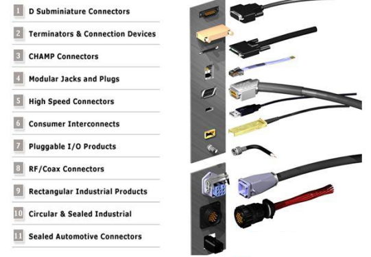
In 1989, with the support of the National Electronic Distributors Association (NEDA, National Electronic Distributors Association, which is an industrial education organization), industry leaders in the production of connectors formulated a connector classification standard and terminology. NEDA Standard classification, this standard developed under the auspices of NEDA is called Levels of Packaging .
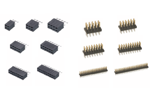
2) Input&Output Connectors
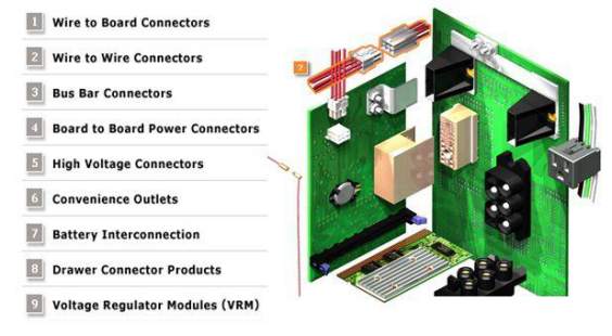
3) Battery connectors
4) Connectors for flat wire
5) RF coaxial connectors
6) Terminal block connectors
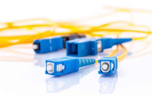
7) S/C Connectors
03. Introduction to the composition and application of the connector
Conductors and connectors: In order to understand the working principle of electronic interconnection components, you need to know some common sense about conductors. When we mention that the conductor communicates the break in the circuit, it actually means that the connector connects the two open ends together. The circuit refers to the entire electrical system, and the conductor is the actual path through which current flows. Sometimes you often can't see the actual conductor because it is covered by insulating or dielectric materials. With dielectric material conductors, they can be arranged in parallel without interfering with each other. The following table describes commonly used conductors.
Picture | Conductor | Application |
| Discrete Wire Single wire or cable | Widely use in a variety of electronics equipment |
| Twisted-wire A cable composed of two small insulated wires twisted together and covered with a sheath. The two wires are usually well insulated. Ordinary telephone cables and household wires are twisted-pair wires. |
computer network telecommunications |
| Coaxial cable It consists of a smaller diameter copper wire (inner conductor) coaxially placed in the larger diameter outer conductor, there is a dielectric isolation and support between the two, their outermost is covered with insulating material. |
Video |
| Ribbon cable The name comes from its appearance resembles a ribbon, also known as a flat cable. It is composed of a group of parallel conductors entirely covered with insulating materials. There are two types of conductors, one is a circular cross-section conductor, and the other is a flat flexible cable. | Computers and peripherals |
| PCB The PCB is printed on a copper-clad polymer board by etching. | Computers and peripherals |
| Flat flexible cable/flat flat circuit (FFC/FPC) It is similar to a ribbon cable, but the conductor is flat, not round. The conductor cross-section is rectangular and extremely thin. | Office equipment, security systems, communications, vending machines. |
| Fiber optic cable There are many types and modes of optical fiber conductors, but the most common are glass, plastic aspiration silicon quartz or plastic, through which light is transmitted or transmitted. | High-speed data transmission, such as computer networks and communication systems |
The connector shown in the picture below is an in-line connector; the characteristic of the in-line connector is that the wire is connected from one half of the connector and the other half is connected. The two parts of the connector are called the plug (male) and the socket (female).
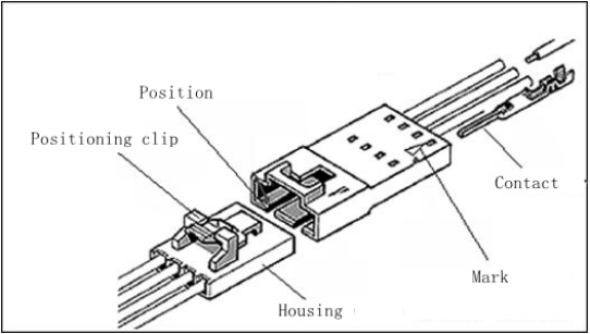
Let's take a look at the various components of the connector below:
The housing of connectors: Its function is to support the contact parts (pins, shrapnel), firmly and correctly in place; prevent dust, dirt and moisture, protect the contact parts and conductors, and insulate the circuits from each other.
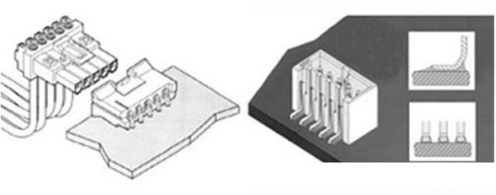
The headers of connectors: This is a connector installed on a printed circuit board. The seat used is called a header, also known as a base or wafer. The main difference between the base and the Housing is that the base is always installed with the circuit pins, while the Housing is just an empty shell. There are two forms of the base: covered and uncovered. The protective cover refers to the pin and socket of the connector, and the protective cover made of the seat body or the protective skirt around the mating part. The base also has a friction lock style. It is a partially covered base but has a locking device, which makes the combination of the base and the base more reliable (see the picture below). There are many bases produced The most commonly used shapes are two shapes: straight pin (also called vertical) and right angle. The number of rows of the base can also be different, it can be a single row of pins, or multiple rows of pins (see the figure below).
Materials used in the connector base:The plastic used in the seat body is thermoplastic, which can be melted and solidified many times. Some also collect the surplus plastic from the molding process and smash it for reuse. The following introduces special plastics used in high temperature environments. This plastic has excellent high temperature resistance. Connectors used for surface mount method of termination (SMT) require this plastic. There is also a surface mount soldering (SMC, surface mount compatible) connector. The difference between the two is that SMC inserts the pins into the via holes and then solders them on the PCB board; while SMT uses solder feet to solder on the surface of the PCB board. Due to the need for welding, the plastic must be able to withstand high temperatures. In other words, the connector housing for surface mounting must be able to withstand high temperatures.
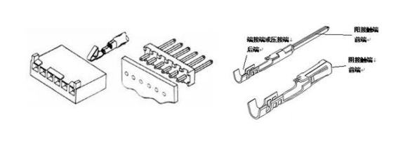
Contacts:The contact part in the connector combines the two conductors (or wires) to be connected together. After bonding, the circuit is closed and current flows through the connector. There are two main types of contacts: terminal and pin. The actual shape of the object varies greatly. The illustrations of both are shown below. The terminal (or pin) has two ends: a front end and a back end. The front end is always the bonding end, which intersects with another terminal to form contact, and the back end always plays the role of termination, or crimping or connecting wires (conductors) .
Connector finished(plating):Electroplating the contact part of the connector is to improve conductivity, corrosion resistance and abrasion resistance, and improve solderability. Metals with good mechanical properties (such as formability and elasticity) often do not have excellent electrical conductivity, corrosion resistance and wear resistance, and weldability. All or selective plating of these metal materials to improve performance. The following table summarizes the main plating metals and their characteristics.
Positioning and keys:Connectors are often multi-pin and socket holes, so it is necessary to ensure that the pins are properly seated. If the operator is negligent, it should not be inserted in order to prevent incorrect or reverse insertion, which may cause circuit accidents. This problem can be solved by so-called positioning devices or keys. The two methods are technically different. The following specifically introduces an example of the plastic seat body guaranteeing unique number-matching insertion (see the figure below). Technically speaking, method 1 is positioning, method 2 is key, and method 3 is a combination of positioning and key. Both are to ensure that the two halves of the connector are correctly mated. The oblique angle of the contact cavity is guaranteed: it ensures that there is only one way of inserting and engaging.
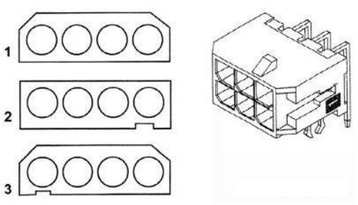
Circuit identification(mark):Because the connector always has many circuit pins, there must be a way to enable the user to correctly confirm the circuit pin number. The following figure introduces two commonly used methods for identifying circuit pin numbers. The base on the left uses a triangle to indicate the starting point of the circuit pin number. This method is very versatile. The base on the right uses the specific circuit pin number "1" to indicate the starting point of the number.

04. Electrical performance of the connector
The main electrical properties of the connector include contact resistance, insulation resistance and dielectric strength.
▶Contact resistance:
High-quality electrical connectors should have low and stable contact resistance. The contact resistance of the connector ranges from a few milliohms to tens of milliohms.
▶Insulation resistance:
An index to measure the insulation performance between electrical connector contacts and between contacts and shells, ranging from hundreds of megohms to thousands of megohms
▶Dielectric strength or withstand voltage, dielectric withstand voltage,
It characterizes the ability to withstand the rated test voltage between the connector contacts or between the contacts and the shell.
▶Other electrical properties
The electromagnetic interference leakage attenuation is to evaluate the electromagnetic interference shielding effect of the connector, and the electromagnetic interference leakage attenuation is to evaluate the electromagnetic interference shielding effect of the connector. It is generally tested in the frequency range of 100MHz~10GHz; for radio frequency coaxial connectors, there is also characteristic impedance. , Insertion loss, reflection coefficient, voltage standing wave ratio (VSWR) and other electrical indicators. Due to the development of digital technology, in order to connect and transmit high-speed digital pulse signals, a new type of connector, namely high-speed signal connector, has appeared. Accordingly, in terms of electrical performance, in addition to characteristic impedance, some new electrical indicators have also appeared. , Such as crosstalk (crosstalk), transmission delay (delay), time lag (skew), etc.
05. The physical properties of the connector
Common environmental performance includes low temperature, constant damp heat, alternating damp heat, salt spray test, sulfur dioxide test, hydrogen sulfide test
▶Temperature resistance:
At present, the maximum working temperature of the connector is 200℃ (except for a few high-temperature special connectors), and the lowest temperature is -65℃. When the connector is working, the current generates heat at the contact point, which causes a temperature rise. Therefore, it is generally believed that the working temperature should be equal to the sum of the ambient temperature and the temperature rise of the contact point. In some specifications, the maximum temperature rise allowed by the connector under the rated operating current is clearly specified.
▶Humidity resistance
The intrusion of moisture will affect the insulation performance of the connection h and rust metal parts. Constant heat and humidity test conditions are relative humidity 90%-95% (according to product specifications, up to 98%), temperature +40±20℃, and the test time is according to product specifications, at least 96 hours. The alternating damp heat test is more stringent.
▶Salt spray resistance
When the connector is working in an environment containing moisture and salt, the surface treatment layer of its metal structural parts and contact parts may produce galvanic corrosion, which affects the physical and electrical properties of the connector. In order to evaluate the ability of electrical connectors to withstand this environment, a salt spray test is specified. It is to hang the connector in a temperature-controlled test box, and spray out a sodium chloride solution of a specified concentration with compressed air to form a salt spray atmosphere. The exposure time is specified by the product specification and is at least 48 hours.
▶Vibration and shock
Vibration and shock resistance is an important performance of electrical connectors. It is particularly important in special application environments such as aviation and aerospace, railway and road transportation. It is an important index for testing the robustness of electrical connectors’ mechanical structure and electrical contact reliability. . There are clear regulations in the relevant test methods. In the shock test, the peak acceleration, duration and shock pulse waveform, as well as the interruption time of electrical continuity should be specified.
▶Other environmental performance
According to the requirements of use, other environmental properties of electrical connectors include sealing (air leakage, liquid pressure), liquid immersion (resistance to specific liquids), low air pressure, etc.


