
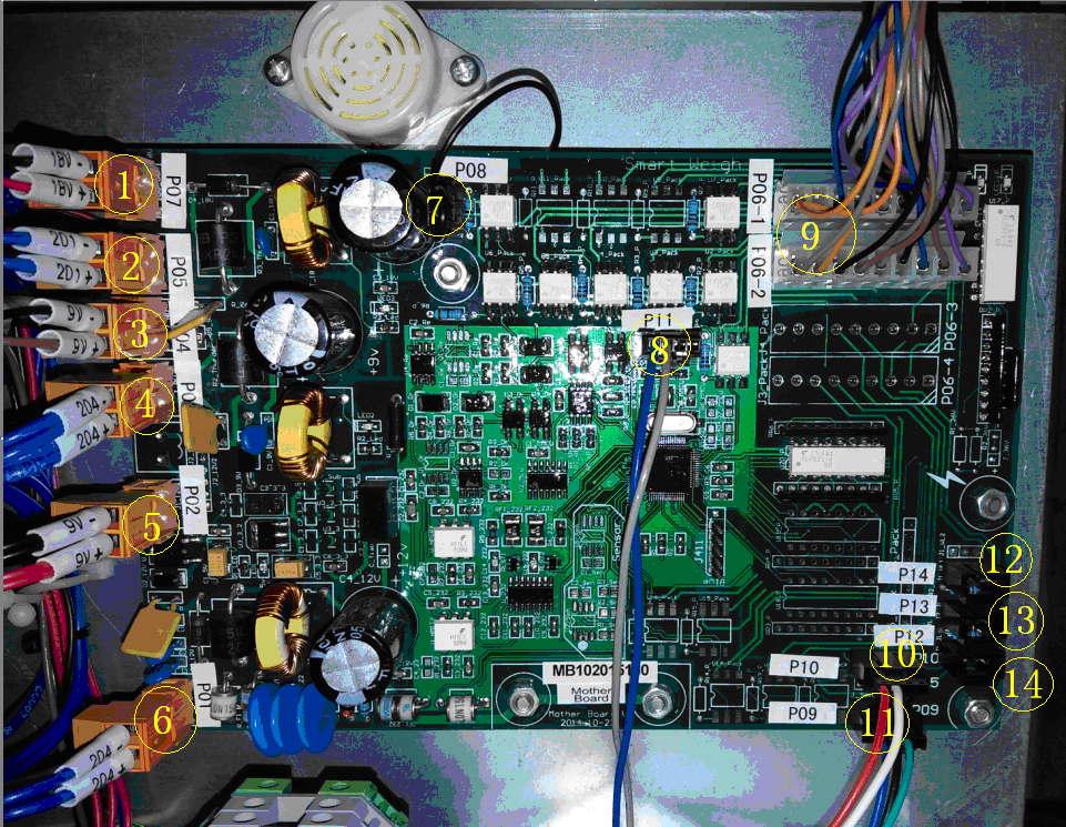
Main board(mother board)
1.Output DC18V, supply the power to the position transfer board and the drive board (big base board)
2.Input DC18V
3.Output DC9V, supply the power to the modular transfer board and the modular.
4.Input DC9V
5.Output DC0V, supply the power to the drive board.
6.Input DC9V, supply power to the main board
7.Buzzer output
8. Modular communication signal line
9. External signal output
10. Drive board communication signal line.
11. Touch screen communication signal line
12. Client’s product position-eye sensor signal line
13.Reserved interface
Big Base Board and Drive Board
1.Input of photo sensor signal line
2.Input DC18V, power supply of photo sensor signal
3.Input DC9V, power supply of drive board
4.Input DC36V, power supply of step motor
5. Feed hopper motor line output
6.Weigh hopper motor line output
7.Lin feeder vibrator power output.
8.Drive board communication line input
9.Input AC110V, power supply of lin feeder vibrator
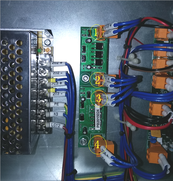
Power Conver Board
1. Input DC24V
2. Output DC18V, power supply of photo sensor
3.Input DC12V
4. Output DC9V, power supply of main board and module
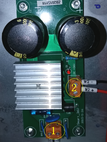
Rectifying Plate
1. Input AC20V
2. Output DC36V,power supply ofstepmotor
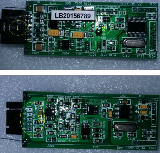
Module
1. Module line plug
2. Module jump area
3. Load sensor line welding position
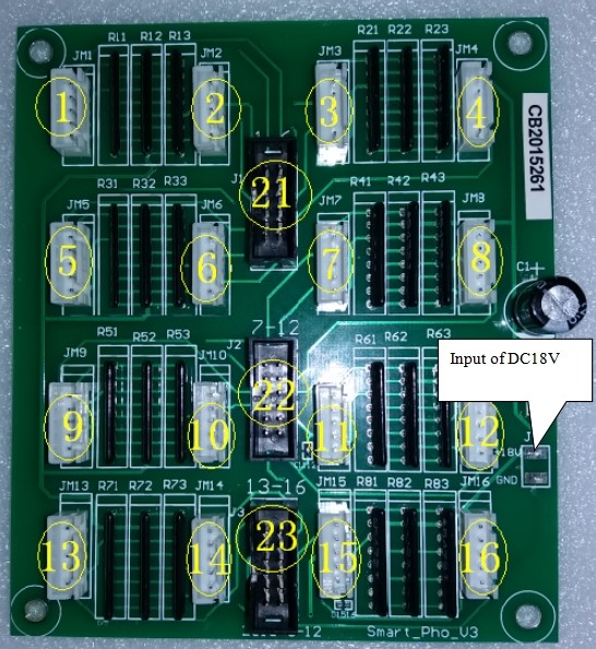
Step Motor Position Board
1.Between 1~ 16, the signal line is detected to be connected to the aluminum specimen box
2.Connect to the signal bus of the big backplane and control the box 1 to 6
3.The signal bus connected to the big base board, controls the aluminum specimen box from 7 to 12
4.The signal bus connecting to the big base board, controls the aluminum specimen box 13 to 16